Galvo Drift and Laser Power Degradation in Long-Hour Metal 3D Printing
Mitigating Thermal Drift and Laser Power Attenuation in Metal 3D Printing
During continuous metal 3D printing runs over 50 hours, heat buildup creates two major problems inside the metal 3D printer. First, galvanometer motor heating shifts the laser spot coordinates by 20 to 50 $\mu\text{m}$. Second, optical thermal lensing and diode aging drop effective laser power density by 3% to 8%. Industrial systems fix this by using three core tools: active liquid-cooled galvanometers, real-time closed-loop power control with photodiodes, and automated pre-build optical grid calibration.
Physics of Optical Drift Across Extended Metal 3D Printing Cycles
Production-grade metal 3D printing often runs continuously for 50 to 150 hours. These long jobs build large parts like rocket chambers, turbine cases, and medical implants. Over several days, heat builds up inside the optical train. This heat changes the beam focus, position, and energy delivery across the powder bed of your metal 3D printer.
Galvo Motor Heating and Thermal Expansion
A powder-bed metal 3D printer uses moving-magnet galvanometer scanners to direct the laser beam. These scanners run at high mark speeds between 1,000 mm/s and 4,000 mm/s. The internal copper voice coils generate continuous electrical heat. Over long print jobs, the internal motor temperature often rises from room temperature to more than 60°C.
This heat expands the motor shaft, mechanical bearings, and mirror mounts. The expansion shifts the baseline reading of the optical or capacitive position encoders. A tiny angular shift of only $0.005^{\circ}$ causes a 20 to 50 $\mu\text{m}$ spot shift at the edge of a 400 × 400 mm build plate. This issue is called galvanometer thermal drift. It causes stepped edges between layers, creates stitch seams in multi-laser systems, and increases internal residual stress in the finished parts.
Thermal Lensing Effect in Protective Optics
While galvanometer motors drift mechanically, the optical lenses also distort. High-power continuous fiber lasers (500W to 1,000W) pass through beam expanders, focus lenses, and quartz protective glass. The optics absorb a small amount of laser light and begin to warm up.
At the same time, the protective glass collects airborne condensate, metal vapor, and spatter from the melt pool. The laser beam heats these surface particles rapidly. This creates a sharp temperature difference between the center and edges of the glass. Because heated fused silica bends light more strongly ($\mathrm{d}n/\mathrm{d}T > 0$), the flat window acts like a curved lens. This problem is known as the thermal lensing effect.
Thermal lensing shifts the focal plane downward along the z-axis by 1.0 to 3.5 mm. As the focus moves away from the powder surface, the nominal 80 $\mu\text{m}$ laser spot expands by 15% to 30%. This expansion dilutes the peak power density:
$$I_{\text{peak}} = \frac{2P}{\pi \omega_0^2}$$
Lower power density reduces the volumetric energy delivered to the metal powder. As a result, the melt pool turns shallow and unstable, causing severe lack-of-fusion defects and internal pores during metal 3D printing.
Laser Diode Degradation & Power Fluctuation
Laser stability is just as critical as beam alignment. Industrial fiber lasers use semiconductor pump diodes that lose output efficiency under long thermal and electrical loads. Without active feedback, laser modules suffer a laser power attenuation of 3% to 8% over multi-day print runs.
In addition, shiny metal powders like aluminum (AlSi10Mg) and copper (CuCrZr) reflect laser light back into the optical chain. These back-reflections cause power ripples and noise. In precision metal 3D printing, a 5% drop in laser power reduces linear energy input ($E_l = P / v$) below the melting threshold. The laser then fails to fully fuse the previous layer, which creates weak bonding and lowers part fatigue life.
3 Engineering Solutions Implemented in Modern Metal 3D Printers
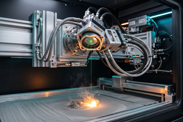
Industrial metal 3D printers use three dedicated engineering solutions to stop drift and keep laser energy steady across long runs.
1. Active Liquid-Cooled Galvanometers
Air cooling cannot handle the high heat loads of long production runs. High-end systems place the galvanometer scanners inside liquid cooling jackets connected to a digital chiller.
- Stable Operating Temperature: Deionized water flows around the motor stators and bearings. This circuit keeps scanner core temperatures locked at $22.0^{\circ}\text{C} \pm 0.5^{\circ}\text{C}$ regardless of scan speeds.
- Silicon Carbide Mirrors: Mirrors use silicon carbide (SiC) or single-crystal silicon instead of standard quartz. These materials conduct heat quickly ($>150\text{ W/m}\cdot\text{K}$) and barely expand when heated.
- Thermal Isolation Mounts: Ceramic thermal breaks separate the galvo mounting plate from the hot build chamber ($200^{\circ}\text{C}–500^{\circ}\text{C}$). This stop prevents chamber heat from warping the optical frame.
By keeping the scanner temperature constant, liquid cooling holds beam drift below $\pm 5\,\mu\text{m}$ over 100 continuous hours on an enterprise metal 3D printer.
2. In-Situ Real-Time Power Closed-Loop Control
To correct laser power attenuation and dirty window losses, modern machines run in-situ photodiode monitoring with fast digital feedback loops.
A beam splitter inside the optical head directs 0.1% of the laser beam into a high-speed silicon photodiode. Sampling at over 100 kHz, the sensor reads laser power right before the beam hits the galvo mirrors. When the sensor detects a drop from window dirt or diode heat, an onboard FPGA controller boosts pump diode current within microseconds.
This closed-loop optical calibration keeps laser energy delivered to the powder bed within a tight $\pm 1.0\%$ window. It stabilizes melt pool volume and ensures uniform grain structure in modern metal 3D printers.
3. Pre-Build Automated Optical Grid Calibration
Automated camera routines replace error-prone manual beam alignments before every long build.
Advanced metal 3D printing machines build high-resolution sensors and optical targets directly into the frame around the powder bed:
- Grid Scanning: The scan head fires the laser across an 81-point reference target before starting a job.
- Spot Centroid Measurement: Embedded sensors measure the beam profile, beam center, and spatial distortion across the build field.
- Automatic Software Correction: The controller recalculates field distortions and coordinate offsets in under 5 minutes without opening the inert build chamber.
This calibration fixes mechanical settling and thermal drift. It keeps laser overlap error within $\pm 10\,\mu\text{m}$, protecting multi-laser production runs against dimensional errors.
Conclusion
Optical stability is the single most critical factor in serial metal 3D printing. Implementing active liquid galvo cooling, in-situ real-time power closed loops, and pre-build automated calibration eliminates thermal drift and energy attenuation, consistently delivering parts with $\ge 99.9\%$ density and micron-level precision.
Ready to benchmark your systems for mission-critical, long-duration builds? Connect with our application engineers today to request the full Optical Stability & FAT Verification Guide and safeguard your serial production.