Dynamic Focus vs. Fixed Spot: How Beam Sizing Impacts Metal 3D Printer Speed and Finish
Dynamic Focus vs. Fixed Spot Capabilities in Metal 3D Printing
Fixed-spot optical systems force a trade-off between surface detail and speed during metal 3D printing. A standard fixed optical train locks the laser beam to a single spot diameter. In contrast, dynamic beam sizing lets a modern metal 3D printer adjust spot size continuously. The laser switches smoothly between a $50\,\mu\text{m}$ fine contour spot and a $300\text{–}500\,\mu\text{m}$ bulk core spot. This dual capability maintains fine surface finish ($Ra < 5\,\mu\text{m}$) while boosting volumetric build rates by 200% to 400%.
| Optical Parameter | Fixed-Spot System (70–100μm) | Dynamic Focus System (50–500μm) |
| Contour Resolution ($Ra$) | $4\text{–}8\,\mu\text{m}$ | $3\text{–}5\,\mu\text{m}$ |
| Volumetric Build Rate | $15\text{–}35\text{ cm}^3\text{/h}$ | $60\text{–}140\text{ cm}^3\text{/h}$ |
| Minimum Wall Thickness | $100\,\mu\text{m}$ | $80\,\mu\text{m}$ |
| Hatch Spacing Range | $0.08\text{–}0.12\text{ mm}$ | $0.25\text{–}0.60\text{ mm}$ (Core) |
| Laser Power Utilization | 400W–500W limit | Scales to 1,000W+ |
The Trade-Off in Fixed-Spot Metal 3D Printers
Traditional laser powder bed fusion platforms rely on a fixed optical path. The optical train focuses the laser beam to a single diameter at the powder bed. This design creates a severe performance bottleneck across production builds.
The Fine-Spot Bottleneck
A static $70\,\mu\text{m}$ beam produces sharp geometric edges and fine surface features. The narrow beam keeps melt pool volume small. Therefore, the system resolves tiny cooling channels and thin structural walls easily.
However, this small spot size slows down internal solid hatching. A fine beam requires narrow hatch spacing between adjacent scan tracks. The laser must scan thousands of parallel lines to melt one heavy solid layer. The galvanometer mirrors sweep repeatedly for hours across bulky internal geometry. This low build rate extends print times and increases operating costs.
The Large-Spot Compromise
Some manufacturing systems use a fixed wide beam diameter ($>200\,\mu\text{m}$) to increase build speed. A wide beam creates a broad melt track. The system melts wider powder lanes on each pass, reducing total scanning exposure time.
Unfortunately, this broad beam damages surface finish and fine dimensional accuracy. The large beam diameter increases the minimum printable feature size. It creates rough stair-stepping marks along curved exterior walls. The wide beam also overheats thin walls, causing melt pool collapse. Machine operators must spend extra machining time on CNC finishing passes.
How Dynamic Beam Sizing Works in Modern Metal 3D Printers
Dynamic beam sizing eliminates the trade-off between build speed and surface resolution. Modern metal 3D printers use high-speed optical elements to alter beam diameter during the build process.
High-Speed Optical Zoom Mechanics
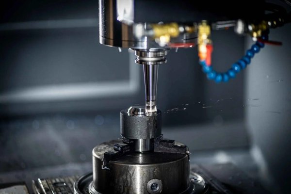
A dynamic optical assembly uses high-speed linear voice coil actuators along the beam path. Other designs use varifocal piezo-actuated lenses. The motion controller shifts lens positions inside the collimator within 5 to 10 milliseconds.
These fast lens movements change beam divergence before laser light reaches the galvanometer mirrors. The optical head expands or shrinks the focused spot directly on the powder surface. The controller synchronizes optical zoom shifts with galvanometer mirror movements. The laser changes spot size instantly when transitioning from thin perimeters to wide internal infill areas.
Contour-Core Partitioning Strategy
Dynamic beam sizing software divides each 2D layer slice into distinct parameter zones. The slicing algorithm separates outer boundaries, inner sub-skin contours, and the massive interior core.
The system traces outer perimeters using a focused $50\,\mu\text{m}$ spot at moderate laser power. This narrow beam produces crisp geometric edges and smooth surface roughness. Once the scan head reaches the internal core volume, the optics expand the spot to $400\,\mu\text{m}$. The machine increases laser power to 1,000W and expands hatch spacing. This strategy melts large internal volumes quickly without sacrificing exterior surface detail.
Energy Density and Melt Pool Matching
Expanding the laser spot diameter requires active energy control to prevent internal flaws. As beam radius ($\omega_0$) expands, peak laser irradiance drops rapidly based on Gaussian physics:
$$I_{\text{peak}} = \frac{2P}{\pi \omega_0^2}$$
To maintain consistent powder melting, the machine controller scales laser wattage with spot surface area. It also adjusts scan speed and layer thickness settings simultaneously.
This energy balancing keeps volumetric energy density ($E_v$) within a stable processing window. It maintains a stable conduction-mode melt pool during wide hatching passes. The balanced power input avoids keyhole porosity while eliminating cold-lap lack-of-fusion voids between scan vectors.
ROI and Performance Benchmark: Real-World Case Studies
Manufacturing facilities running metal 3D printers with dynamic focus optics achieve substantial improvements in production throughput.
Automotive Die & Tooling Case Study
A tooling shop manufactured an H13 steel mold insert with internal conformal cooling lines. The component required smooth inner cooling channels ($Ra < 6\,\mu\text{m}$) alongside an 18 kg solid mounting base.
- Fixed-Spot Baseline: A standard $80\,\mu\text{m}$ fixed-spot machine completed the build in 48 hours and 20 minutes.
- Dynamic Focus Run: The dynamic focus system processed cooling channels at $60\,\mu\text{m}$ and core sections at $350\,\mu\text{m}$.
- Throughput Result: Total build time dropped to 19 hours and 10 minutes, cutting total machine run-time by 60.4%.
- Cost Savings: The customer saved $1,450 in direct machine operating costs per mold insert.
Metallurgical Density and Mechanical Isotropy
Parts printed with dynamic beam sizing match or exceed traditional quality standards. Metallurgical testing confirms that active spot expansion maintains complete material density throughout all sections.
- Relative Density: Archimedes density testing and optical microscopy confirm a relative density of $\ge 99.95\%$.
- Tensile Properties: Dynamic-focus Inconel 718 test bars match baseline values across horizontal and vertical axes (Yield Strength: $1,120\,\text{MPa}$, UTS: $1,380\,\text{MPa}$, Elongation: $14.5\%$).
- Interface Bonding: Scanning electron microscopy shows defect-free metallurgical bonding across contour-core transitions without micro-cracking.
Conclusion & Slicing Parameter Consultation
Dynamic beam sizing delivers clear economic advantages for serial production. Equipping an industrial metal 3D printer with dynamic focus optics removes the trade-off between build speed and finish. Shops produce large structural parts in less time while meeting strict surface roughness standards.
Do you want to scale production throughput on your manufacturing floor? Contact our engineering team today to request a dynamic focus benchmark demonstration. You can also download our full Dynamic Beam Slicing & Process Parameter Guide.