Hidden Costs of Argon Consumption and Gas Recirculation in Metal 3D Printers
The hidden costs of argon consumption in a production Metal 3D Printer stem directly from continuous gas venting, optical window purge requirements, and inefficient open-loop filtration systems. While buyers typically focus on machine depreciation and metal powder prices, continuous argon usage adds significant, recurring operational costs that scale with machine runtime and chamber volume. This guide breaks down the true cost of inert gas consumption across every production phase, compares open-loop venting with closed-loop gas recirculation architectures, and examines in-line purification to help facilities minimize recurring utility expenditures.
Facility managers frequently encounter unexpected operating budget spikes because identical build volumes can exhibit a five-fold variance in gas consumption across different machine architectures. An open-loop platform that exhausts shielding gas directly can consume thousands of liters of high-purity argon per build cycle. Conversely, an advanced closed-loop Metal 3D Printer cleans and recirculates inert atmosphere continuously, reducing consumption by up to 90%. Understanding gas consumption dynamics across every operating phase allows procurement managers to identify hidden facility costs before finalizing equipment acquisitions.
Breakdown of Argon Consumption Phases in a Metal 3D Printer
Argon consumption is not constant throughout an additive production run. Operating a commercial Metal 3D Printer involves three distinct operational phases, each presenting unique volumetric demands and pressure requirements.
| Operational Phase | Average Gas Flow Rate | Primary Purpose | Cost Impact Factor |
| Chamber Purge Phase | 40 – 80 L/min (Initial flush) | Ambient air displacement to < 100 ppm $O_2$ | High burst volume, driven by chamber cubic volume |
| Process Flow Phase | 2 – 10 L/min (Closed-loop) / 30 – 60 L/min (Open-loop) | Laminar melt pool protection and soot evacuation | Sustained operational run rate throughout build |
| Optical Air Knife | 5 – 15 L/min (Continuous) | High-velocity barrier protecting quartz window | Continuous non-recirculated or filtered parasitic draw |
Initial Chamber Purge Phase
Before laser emission starts, the build chamber must transition from ambient atmosphere containing 210,000 ppm oxygen down to an ultra-pure environment below 100 ppm. In standard systems relying on dynamic displacement, heavy argon gas is injected at high volume flow rates (often 40 to 80 L/min) to displace lighter atmospheric air through lower exhaust ports.
For a medium-sized build volume (such as 250 x 250 x 350 mm), displacing the internal volume and internal ducting typically consumes between 800 and 2,500 liters of argon gas. If the mechanical enclosure features internal dead zones or unsealed expansion joints, purge cycles can take over an hour and consume more than 4,000 liters before baseline oxygen specifications are verified.
Continuous Process Flow Phase
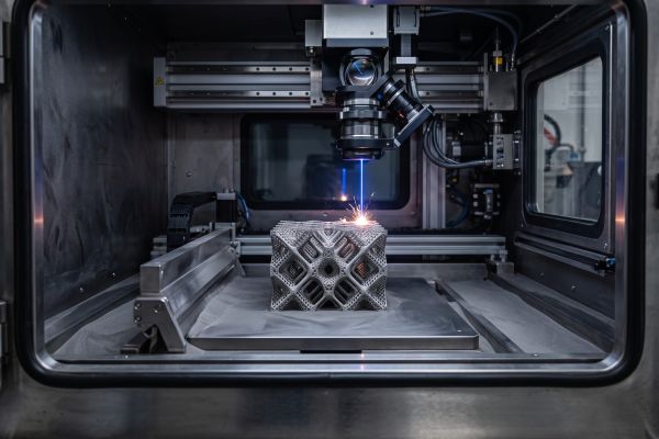
Once exposure commences, a continuous flow of inert gas must pass over the powder bed. This laminar stream prevents oxygen re-entry, stabilizes melt pool thermodynamics, and carries away metallic smoke, condensate, and vaporized nanoparticles. In open-loop machinery, this gas stream vents directly to the facility exhaust, requiring constant injection of fresh, high-purity gas. Over a 50-hour production run, an open-loop system consuming 35 L/min expends 105,000 liters of argon.
Optical Protection Air Knife and Auxiliary Operations
The optical protective glass sits directly above the active melt pool. To prevent metallic condensate from settling on the optical surface and attenuating laser power, a high-velocity gas knife directs a focused curtain of inert gas across the window face.
Additionally, auxiliary gas is consumed during pneumatic glovebox operations, powder overflow clearing, and chamber depressurization sequences. These secondary gas draws represent continuous parasitic consumption that accumulates significantly across continuous 24/7 operating schedules.
Open-Loop vs. Closed-Loop Gas Recirculation in Modern Metal 3D Printers
The architectural divide between open-loop exhaust designs and closed-loop recirculation systems represents the single largest determining factor in factory gas utility expenditures.
Open-Loop Gas System Architecture
Early powder bed fusion systems and budget-tier machines utilize open-loop gas delivery due to simplified mechanical engineering requirements:
- Fresh liquid or gaseous argon feeds directly from external storage through a pressure regulator.
- Gas sweeps across the build chamber to collect welding fumes and condensate.
- The contaminated stream routes through an exhaust particulate filter and vents straight out of the building.
While open-loop designs eliminate the need for expensive internal blowers and cooling heat exchangers, they create high operational costs. Industrial Metal 3D Printers operating on open-loop architectures continuously consume fresh gas at rates between 25 and 50 L/min throughout the entire duration of active laser scanning.
Closed-Loop Recirculation Architecture
Modern production-grade Metal 3D Printers utilize fully sealed closed-loop recirculation systems that capture, filter, and reuse shielding gas indefinitely:
- High-Efficiency Roots or Regenerative Blowers: A hermetically sealed, variable-frequency drive blower circulates internal argon gas across the powder bed without introducing ambient air contamination.
- Dual-Stage Mechanical Filtration: Gas containing process soot passes through coarse cyclonic pre-separators and sub-micron primary cartridge filters, capturing airborne particulate before gas returns to circulation.
- Integrated Heat Exchangers: Laser radiation, preheated baseplates, and mechanical blower friction add continuous heat to circulating gas. Integrated water-cooled heat exchangers drop gas temperatures back down to 20°C to 24°C, preventing thermal distortion of internal optics and kinematic drive stages.
By recycling cleaned gas, a closed-loop system only draws fresh argon to compensate for minor micro-leaks and pneumatic overpressure maintenance. Operating consumption drops from 35 L/min down to 0.5 to 2 L/min, reducing continuous process gas usage by 80% to 95%.
Gas Purity Degradation and In-Line Purification Solutions
Operating a closed-loop Metal 3D Printer reduces volumetric consumption, but recirculating the same gas volume introduces secondary contamination risks that affect metallurgical quality.
Chemical Contamination Accumulation
As inert gas circulates through the mechanical loop, it encounters recycled metal powder beds that release absorbed atmospheric moisture. High-temperature laser melting also accelerates the desorption of volatile compounds.
Over extended multi-day manufacturing campaigns, moisture levels within closed circuits can rise from an initial 5 ppm up to several hundred ppm. While the oxygen sensor may read within specification, moisture ($H_2O$) breaks down under laser plasma into free hydrogen and oxygen, causing hydrogen-induced porosity in aluminum and titanium lattices.
In-Line Deox and Dryer Purification Systems
To mitigate chemical degradation without venting expensive argon, advanced Metal 3D Printing setups integrate in-line regenerative purification columns:
- Molecular Sieve Moisture Traps: Zeolite desiccants selectively adsorb water vapor molecules down to dew points below -70°C, maintaining absolute humidity levels below 1 ppm.
- Catalytic Deox Scrubbers: Heated copper or palladium catalyst beds react with trace oxygen molecules, chemically binding impurities before gas re-enters the processing chamber.
- Economic Value: Integrating in-line purification hardware eliminates gas dump-and-flush cycles while preventing rejected builds, stabilizing recurring utility costs for operations processing reactive alloys like Ti-6Al-4V.
Evaluating Gas Efficiency When Procuring a Metal 3D Printer
Understanding the long-term utility footprint of industrial equipment prevents operational budget overruns:
- Calculate total gas consumption including dynamic purge requirements, continuous process flow, and optical window protection.
- Confirm that closed-loop architectures incorporate integrated water-cooled heat exchangers to maintain thermal stability across the gas loop.
- Verify whether the manufacturer integrates internal moisture monitoring alongside primary oxygen sensors to track chemical purity.
- Ensure the filtration and recirculation circuits maintain stable laminar gas velocity across the full width of the powder bed.
Optimizing gas flow engineering, recycling loops, and purification columns transforms shielding gas management from an unpredictable operating expense into an optimized manufacturing standard.
Contact our application engineering team to evaluate closed-loop operational savings and plan gas utility layouts for your production facility.