How Does Laser Spot Size Affect Metal 3D Printing?
Laser Spot Size Influences the Area of Material Being Melted
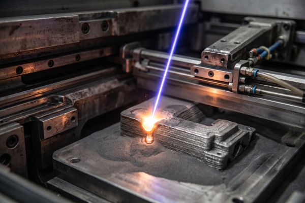
In metal 3D printing, laser spot size directly controls molten pool width, minimum printable feature boundaries, and volumetric processing rates. Laser spot size defines the optical beam diameter focused at the powder bed plane, typically measured at $1/e^2$ beam intensity.
This optical dimension establishes the physical boundary where coherent light couples into metal powder. It determines whether radiant heat resolves fine thin-walled fins or drives rapid deposition across dense structural cores.
Smaller Laser Spots Support Fine Features
Narrow beam diameters ($40\text{–}70\,\mu\text{m}$) concentrate optical intensity into tight coordinates, enabling fine detail resolution. Industrial metal 3D printers utilize narrow spots to define crisp component borders:
- Sharp Exterior Boundaries: Small optical waists trace part edges with minimal lateral heat bleed, yielding as-built surfaces with lower arithmetic roughness.
- Thin Solid Walls: A concentrated spot reliably melts standalone partitions down to $0.25\,\text{mm}$ without structural slump.
- Complex Micro-Channels: Tight beams prevent loose particles from sintering inside narrow internal conduits, preserving open flow paths below $0.5\,\text{mm}$ in diameter.
Adhering to the ISO/ASTM 52911-1 standard requires matching beam waist limits to component geometry to avoid geometrical over-melting.
Larger Laser Spots Can Support Higher Material Deposition
Expanding the optical diameter ($100\text{–}250\,\mu\text{m}$) broadens the contact zone between laser energy and the powder layer. A wider beam produces a larger melt pool, melting more powder volume in a single linear pass.
On a multi-laser metal 3D printer, wider beams accelerate build speeds when printing bulky structural blocks or tooling dies. Slicing with a wider optical diameter widens hatch spacing, substantially reducing the total vector path distance needed to consolidate internal bulk regions.
Spot Size Also Affects Energy Distribution in Metal 3D Printing
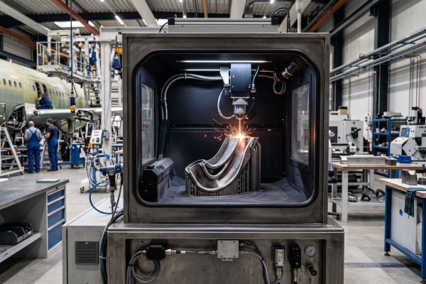
Altering optical waist diameter changes the delivered peak power density at the center of the beam. A standard single-mode laser typically delivers a Gaussian beam profile where energy concentrates heavily in the center.
When the spot size shrinks without adjusting power, peak intensity rises sharply. This concentrated flux can vaporize volatile elements and trigger unstable keyhole porosity. Conversely, expanding the spot lowers central power intensity. If the energy falls below the threshold needed for continuous melting, unmolten powder pockets form along scan boundaries.
Laser Spot Size Must Match Printing Parameters
Laser spot size cannot function as an isolated parameter. Stable material consolidation requires balancing beam diameter with laser wattage ($P$), scan speed ($v$), layer thickness ($t$), and hatch distance ($h$):
$$\text{VED} = \frac{P}{v \cdot h \cdot t}$$
A larger spot requires greater laser power or slower scan velocities to achieve complete powder consolidation. Slicing engines must also adjust hatch spacing to match pool width, maintaining a $30\%\text{–}50\%$ track overlap to prevent inter-track porosity.
Fixed and Variable Spot Sizes Serve Different Applications
Different metal 3D printers apply distinct optical architectures to balance production speed with surface resolution:
- Fixed-Focus Optics: Maintain a constant spot size throughout the exposure cycle. These systems deliver consistent repeatability and straightforward parameter qualification for single-alloy production.
- Dynamic Beam Shaping: Uses motorized vario-focal elements to adjust beam diameter on the fly.
- Core-and-Contour Strategies: The optical head applies a fine $50\,\mu\text{m}$ beam along delicate perimeter borders, then widens to $150\,\mu\text{m}$ for high-speed interior infill.
This dual-mode exposure eliminates the traditional compromise between fine surface finish and build productivity.
Evaluating Optical Architecture for Production Reliability
Assessing laser spot capability requires looking beyond single brochure dimensions to evaluate full optical system stability. Buyers must examine optical field calibration, thermal drift resistance, and focal depth across the build plate.
A reliable metal 3D printer maintains consistent spot circularity from the platform center to the outer edges. Selecting an optical setup designed for your application profile ensures predictable consolidation across both fine details and solid core sections. Contact our engineering team today to review your CAD geometry and evaluate the ideal laser optical configuration for your parts.