How to Choose the Right Metal 3D Printer for Your Production Needs?
A Metal 3D Printer Should Match Your Production Requirements
To choose the right metal 3D printer, evaluate your specific component geometry, alloy requirements, tolerance thresholds, and annual throughput demands against equipment optical capabilities and operating economics. Selecting equipment based purely on maximum build envelope or peak laser wattage leads to underutilized machinery and excessive unit costs. Successful adoption demands matching industrial metal 3D printing hardware to material compatibility, part precision, and long-term production stability.
- Target Part Geometry: Align chamber volume to part dimensions to avoid unnecessary inerting gas consumption.
- Material Suitability: Confirm open or validated parameter sets for your specific production alloys.
- Throughput Demands: Balance scan speeds against multi-optical architectures to maintain mechanical repeatability.
Define the Materials and Applications Before Choosing
Every manufacturing initiative starts with material qualification. Different metal 3D printers handle reactive and non-reactive powders differently:
- Aerospace & Defense: Demands nickel superalloys (Inconel 718/625) and titanium alloys (Ti6Al4V) requiring inert chambers with oxygen levels $<100\,\text{ppm}$.
- Medical Implants: Requires certified titanium or cobalt-chrome parameter sets to yield biocompatible, porous trabecular structures.
- Automotive & Tooling: Relies on AlSi10Mg aluminum alloys or hardened maraging steels prioritizing high thermal dissipation and wear resistance.
Volume requirements also dictate equipment architecture. R&D prototyping demands agile, open-parameter metal 3D printers that allow rapid powder changeovers. Conversely, serial manufacturing requires dedicated machines locked to single alloys to eliminate cross-contamination risks.
Compare Build Size, Printing Speed, and Productivity
A larger build volume increases nesting capacity but scales operating costs. Heating, inerting, and recoating large build platforms adds non-productive cycle time:
| Parameter | Prototyping / Small-Batch | Mid-Volume Production | High-Volume Serial Production |
| Build Envelope ($X \times Y \times Z$) | $\le 150 \times 150 \times 150\,\text{mm}$ | $250 \times 250 \times 350\,\text{mm}$ | $\ge 400 \times 400 \times 500\,\text{mm}$ |
| Laser Configuration | Single $200\text{–}400\,\text{W}$ Fiber Laser | Dual $500\,\text{W}$ Fiber Lasers | Quad or Octa $500\text{–}1000\,\text{W}$ Lasers |
| Typical Layer Thickness | $20\text{–}40\,\mu\text{m}$ | $30\text{–}60\,\mu\text{m}$ | $60\text{–}100\,\mu\text{m}$ |
| Primary Economic Target | Feature Resolution | Balanced Part Cost | Maximum Deposition Rate |
Raw scan velocity does not equal finished part throughput. Total output in metal 3D printing combines exposure time, recoater transit time, thermal stabilization, and platform preheating.
Evaluate Laser Configuration and Process Stability
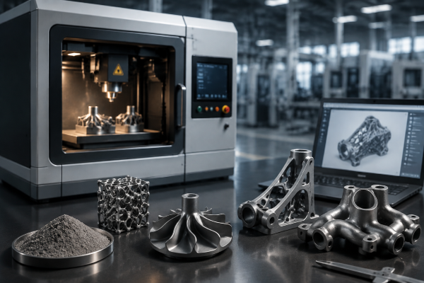
The optical train serves as the core engine of an industrial metal 3D printer. Higher laser power enables thicker powder layers and faster exposure speeds, but beam quality dictates final mechanical density.
Variable or optimized laser spot sizes ($50\text{–}100\,\mu\text{m}$) allow fine contour detail alongside rapid hatch filling. Multi-laser configurations require calibrated scan field overlap boundaries to prevent stitching defects.
Evaluating the galvanometer cooling design and thermal insulation verifies that beam delivery coordinates will not drift during 70+ hour continuous builds. Consistent focus stability ensures predictable metallurgy across every build quadrant.
Consider Accuracy, Surface Quality, and Layer Thickness
Geometric precision directly controls downstream machining and finishing costs. Selecting an industrial metal 3D printer involves balancing layer resolution against production rates:
- Thin Layers ($20\text{–}30\,\mu\text{m}$): Delivers superior surface finishes ($Ra \le 5\text{–}8\,\mu\text{m}$) and fine lattice resolution, ideal for medical or micro-fluidic tooling.
- Thick Layers ($60\text{–}90\,\mu\text{m}$): Multiplies volumetric deposition rates for large industrial structures but increases stair-stepping on angled surfaces ($Ra > 15\,\mu\text{m}$).
Conformity to international ISO/ASTM 52900 standards ensures that dimensioning tolerances ($\pm 0.1\text{–}0.2\,\text{mm}$ or $\pm 0.2\%$) remain consistent from build to build.
Check Powder Handling and Operating Requirements
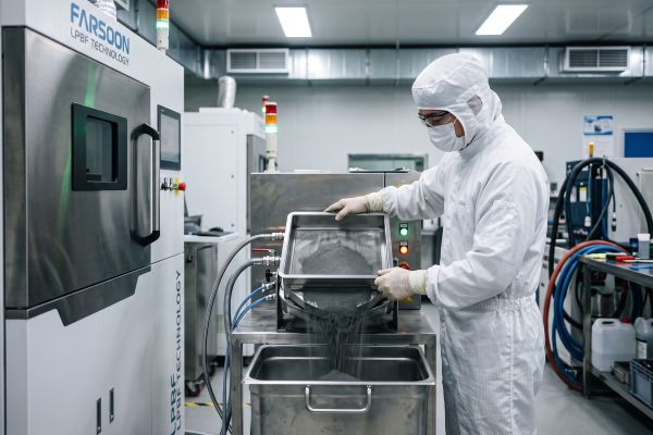
Effective operation extends beyond laser sintering. Safe handling of micro-fine metal powders requires closed-loop peripheral infrastructure:
- Inert Gas Management: Recirculating filtration systems with dynamic laminar gas flow protect melt pools from soot accumulation during the laser powder bed fusion process.
- Closed-Loop Powder Feeding: Automated sieving and ultrasonic convey systems minimize operator powder exposure and preserve powder morphology.
- Facility Preparedness: Dedicated ATEX/NFPA-compliant spaces, inert argon supplies, and explosion-proof vacuums are mandatory for reactive powder usage.
Reliable powder reclamation systems directly lower feedstock scrap rates, maximizing long-term operating profitability.
Choose a Metal 3D Printer Based on the Complete Production Workflow
Do not evaluate a machine based on standalone datasheet metrics. An optimal metal 3D printer balances capital equipment expenditures with post-processing overhead, depowdering tools, wire EDM separation, heat treatment, and quality inspection.
When evaluating different machines, calculate the fully loaded cost-per-part over three years of operation. The most cost-effective metal 3D printer provides stable laser power distribution, reliable recoater mechanics, and streamlined factory acceptance verification, ensuring predictable performance throughout your production lifecycle.Contact our application engineers today to schedule a benchmark build and calculate the exact cost-per-part for your production components.