What Printing Accuracy Can You Expect From a Metal 3D Printer?
Metal 3D Printer Accuracy Depends on Multiple Factors
A production-grade metal 3D printer typically achieves dimensional accuracy between $\pm 0.1\,\text{mm}$ and $\pm 0.2\,\text{mm}$ (or approximately $\pm 0.1\%\text{–}0.2\%$ for larger spans), but no single number applies to every build. True geometric precision is not simply a hardware specification printed on a brochure. It is the end result of interactions between optical calibration, alloy thermal expansion, laser exposure parameters, and component geometry.
Datasheet values represent optical positioning limits under laboratory conditions. Finished parts reflect real-world material shrinkage, localized powder consolidation, and thermal stresses.
Laser Spot Size Influences Fine Features
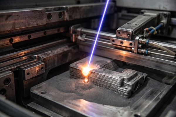
The focused laser beam dictates the minimum detail a machine can resolve. Most industrial metal 3D printers use focused spot diameters between $60\,\mu\text{m}$ and $100\,\mu\text{m}$.
- Melt Pool Broadening: The physical melt track is always wider than the optical beam. A $70\,\mu\text{m}$ spot typically produces a $120\text{–}180\,\mu\text{m}$ molten pool due to conductive heat transfer into surrounding powder.
- Feature Constraints: Spot size limits minimum positive wall thickness (typically $\ge 0.3\,\text{mm}$) and minimum clear channel diameters ($\ge 0.5\,\text{mm}$).
- Beam Offset Compensation: Slicing software applies beam compensation algorithms to shift toolpaths inward. Precise calibration ensures outer edges solidify at the intended nominal boundary.
Layer Thickness Affects Vertical Accuracy
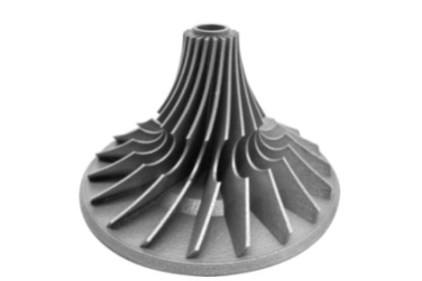
Vertical precision along the Z-axis depends directly on slice height. Standard slice thicknesses of $20\text{–}60\,\mu\text{m}$ determine how closely an industrial metal 3D printer tracks contoured geometry.
Thin layers reduce stair-stepping along gradual slopes. They provide tight tolerances on angled sealing faces and shallow domes. In contrast, thicker layers ($60\text{–}90\,\mu\text{m}$) accelerate build rates but coarsen vertical resolution. This step effect degrades profile accuracy, requiring wider machining allowances on critical interface surfaces.
Thermal Effects Can Change Part Dimensions
Thermal dynamics create the largest dimensional deviations in metal 3D printing. Every laser pass rapidly melts powder and cools at rates exceeding $10^5\,^\circ\text{C/s}$.
This extreme thermal cycling triggers non-uniform volumetric shrinkage. As solidified tracks contract against rigid baseplates, internal stresses build up continuously. High-temperature alloys like Ti6Al4V and Inconel 718 generate intense internal strain. Without proper platform preheating ($>150\text{–}200\,^\circ\text{C}$), residual stress accumulation induces part distortion, corner curling, or substrate warping once components are cut from the build plate.
Part Geometry and Orientation Also Matter
Part shape directly dictates structural rigidity during laser exposure:
- Unsupported Overhangs: Angles below $45^\circ$ trap heat because loose powder acts as a thermal insulator. This causes localized melt pool sag, surface swelling, and out-of-tolerance underside dimensions.
- Dense Solid Masses: Bulky cross-sections accumulate excessive heat. They expand more than adjoining thin ribs, introducing localized dimensional warping.
- Sacrificial Anchors: Robust support structures resist thermal contraction forces. Slicing orientation must balance stress restraint against ease of post-build support removal.
Managing these factors ensures a commercial metal 3D printer prints repeatable, stable geometries.
How Accuracy Is Evaluated in Metal 3D Printing
Verifying dimensional capability requires standardized metrology rather than checking single dimensions on isolated parts.
Engineers evaluate precision by running ISO/ASTM 52902 benchmark artifacts. These test plates include calibrated pin arrays, thin ribs, through-holes, and overhang wedges distributed across the build plate. Optical 3D scanners capture full-field coordinate measurements, generating color-deviation heatmaps against reference CAD files. In high-volume metal 3D printing, true capability is defined by statistical process capability ($Cpk \ge 1.33$) across consecutive production batches, not a single optimal measurement.
Defining Realistic Accuracy for Metal 3D Printing Applications
True precision in metal 3D printing is not a static number on an equipment brochure. It is a dynamic operating window governed by optics, thermal management, and part geometry. For general industrial applications, an operational expectation of $\pm 0.1\text{–}0.2\,\text{mm}$ represents a realistic, repeatable baseline across standard build volumes.
Rather than chasing an absolute theoretical tolerance, engineers must evaluate whether a metal 3D printer maintains stable process repeatability across the entire platform. Achieving tight geometric tolerances ultimately requires harmonizing machine calibration with geometry-specific design rules. Contact our engineering team today to benchmark your component drawings and analyze realistic tolerance limits for your application.