Ceramic vs. Soft Recoater Blades: Crash Protection Strategies for Metal 3D Printers
Ceramic recoater blades deliver rigid layer thickness uniformity within $\pm 2\,\mu\text{m}$ for high-density components, while soft recoater blades made of silicone or carbon fiber flex over upturned features to prevent catastrophic recoater collisions. In industrial Metal 3D Printers, choosing between ceramic and soft blades depends on geometry risk: rigid ceramic edges risk fatal build stoppages when parts curl from thermal stress, whereas soft blades provide vital part curling protection at the expense of minor layer compression. Implementing active torque-sensing loops alongside compliant blade mounts enables modern manufacturing facilities to maintain continuous multi-laser production without unplanned downtime.
| Performance Attribute | Rigid Ceramic Blade (Al2O3 / Si3N4) | Soft Flexible Blade (Silicone / Carbon Fiber) |
| Layer Uniformity Tolerance | High precision ($<\pm 2\,\mu\text{m}$) | Moderate precision ($\pm 5 – 10\,\mu\text{m}$) |
| Crash Vulnerability | Critical; zero mechanical compliance | Excellent; elastic deflection over curling |
| Wear & Abrasion Life | Extended lifespan (up to 500+ hours) | Periodic replacement (100–150 hours) |
| Recommended Part Geometry | Massive solid blocks, flat mold inserts | Thin-wall fins, high-aspect lattices, overhangs |
The Physics Behind Recoater Collisions in LPBF
Mechanical crashes during powder spreading originate from rapid localized phase changes and extreme thermal gradients across the build envelope.
Thermal Stresses and Part Curling
During selective laser melting, localized energy input melts metallic powder while the underlying substrate remains cooler. This localized differential heating creates intense thermal stress throughout the component.
As molten pools solidify and cool rapidly, the top surface undergoes plastic contraction while constrained by underlying solid material. In large overhangs, unanchored overhang contours, and delicate fin structures, these upward forces exceed the yield strength of the material. The edges deform upward by dozens of microns, extending directly into the horizontal traversal path of the spreading assembly. When a rigid wiper attempts to traverse this protrusion, the mechanical collision can break delicate supports, shift the build platform, or trigger a complete system halt in commercial Metal 3D Printers.
Hard Particle Obstructions
Laser interactions do not produce entirely smooth tracks. High vapor-recoil pressure expels molten droplets, forming oxidized spatter particles and heavy slag fragments exceeding 100 microns in diameter.
If these consolidated metal particulates land outside the active scan vector and settle on the raw powder bed, they represent hard, unyielding physical obstacles. A ceramic blade moving across the platform strikes these dense inclusions directly, generating severe horizontal shear forces that can chip brittle ceramic edges or score deep grooves across the entire powder bed.
3 Engineering Crash Protection Strategies in Production
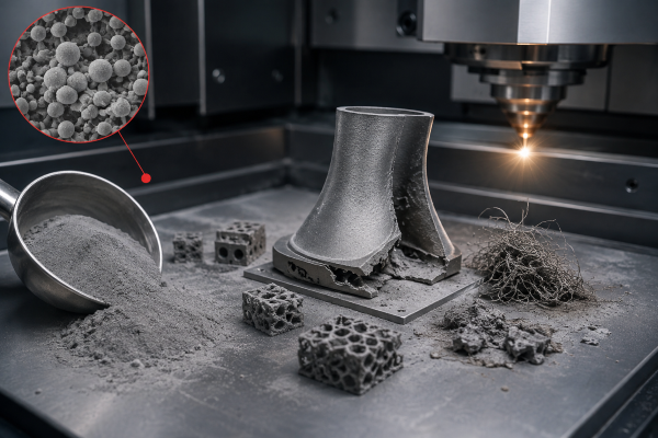
Mitigating mechanical damage requires combining mechanical compliance, active closed-loop motor monitoring, and automated optical validation on every modern Metal 3D Printer.
Compliant Blade Mounting Systems
Traditional rigid toolholders lock the wiper edge securely into a solid linear guide. By contrast, compliant mounting mechanisms introduce engineered degrees of freedom into the toolhead.
Spring-loaded linear pivots allow the recoating assembly to elevate vertically when encountering severe lateral resistance. If an upturned feature exerts vertical force against the edge, the compliant suspension absorbs the peak impact energy and lifts slightly, preventing a destructive ceramic recoater blade crash. Once the assembly clears the obstruction, precision counterweights or linear guide bearings restore the edge to its nominal horizontal datum.
Real-Time Motor Torque & Resistance Monitoring
Modern Metal 3D Printers integrate microsecond closed-loop current feedback directly within the recoater axis servo drives.
- Dynamic Baseline Calibration: The drive system continuously measures the baseline frictional drag of clean powder spreading across every square centimeter of the bed.
- Instantaneous Resistance Detection: A specialized recoater resistance sensor detects sudden current spikes caused by physical interference before mechanical strain bends the recoater carriage.
- Autonomous Retract Sequences: If motor torque spikes by more than 15% above normal thresholds, the motion controller halts forward motion within milliseconds. The drive reverses 5 to 10 millimeters, lowers the build elevator by a microscopic compensation margin, and attempts a secondary low-velocity pass to safely level the area.
In-Situ Optical Powder Bed Anomaly Detection
High-resolution machine vision cameras mounted above the process enclosure inspect the build envelope after every recoating cycle. Structured light or grazing-angle illumination accentuates surface topography defects:
- Deep recoater drag lines indicating a chipped ceramic edge.
- Exposed metallic points indicating severe part curling through the powder layer.
- Localized powder starvation areas caused by wiper chatter.
When optical algorithms identify anomalous reflections, the system halts scanning immediately. This automated loop enables operators running Metal 3D Printing lines to correct defects or execute targeted secondary recoats before high-energy lasers strike unshielded protrusions.
Blade Selection Strategy: Aerospace vs. Tooling Applications
Selecting the correct wiping architecture dictates part yield and surface roughness across divergent industrial sectors operating Metal 3D Printers.
Aerospace Thin-Wall Geometries
Aerospace structures commonly feature high-aspect-ratio turbine blades, complex internal cooling channels, and lightweight lattice matrices. These delicate structures exhibit minimal lateral stiffness during initial build stages.
Applying a rigid ceramic blade against unsupported aerospace geometries poses severe operational risks. If a thin-wall section experiences slight micro-curling, a rigid edge will rip the feature off its build supports. Production lines processing complex aerospace alloys prioritize a flexible silicone recoater blade or carbon-fiber brush. The compliant material deforms elastically over upturned features, ensuring uninterrupted processing of flight-critical hardware.
High-Hardness Tooling and Massive Solids
Conversely, manufacturing hot-work tool steels, large mold inserts, and structural blocks presents minimal curling risk due to heavy anchor supports and substantial thermal mass.
In these applications, using a compliant wiper can cause powder compression variations around dense geometries. Tooling manufacturers deploy rigid ceramic edges made of dense aluminum oxide or silicon nitride to maintain sub-micron layer height consistency. The stiff edge levels heavy alloy powders evenly, minimizing surface roughness and internal porosity across demanding Metal 3D Printing production schedules.
Building Resilient Operations with Advanced Metal 3D Printers
Optimizing recoater blade selection balances dimensional accuracy with operational resilience. While rigid ceramic blades deliver exceptional surface finish and layer uniformity on massive solid parts, soft flexible blades safeguard delicate aerospace structures against expensive crash-related downtime. Combining compliant mechanical tooling with real-time torque sensing transforms fragile powder spreading into a robust, autonomous production process.
Contact our technical engineering team to evaluate recoater tooling configurations and download our comprehensive recoater maintenance whitepaper for your Metal 3D Printer.